A picture tells a thousand words, and that is why welding symbols are a key part of any construction plan. They’re designed to be understood by everyone from the architect to the foreman to the welder themselves so that everybody knows what’s going on through the whole process without any misunderstandings. Knowing key weld symbols and what they mean can be the difference between a highly successful project and a mediocre result or even failure.
The symbols used in blueprints are used to specify exactly what and where the weld needs to be, designed in a graphical manner that overcomes linguistic differences and other misunderstandings. Once you’ve mastered the art of reading, understanding, and applying weld symbols to your own work, you’re well on your way to professional welding success.
In any sort of construction or manufacturing, the most important thing is to be properly, carefully, and fully prepared in every way possible. This means having the right equipment and tools, the right goals, and of course, knowing exactly where your welds need to be. If you don’t have everything ready, then the end project will always suffer for it.
For a beginner welder, even the most basic weld symbols might feel a little overwhelming, but learning the ins and outs of these welding symbols is essential to success. If you’re just starting out, be sure to also check out our article on the best welder for beginners. Even seasoned welders can have some trouble with symbols, which is why this article is here to help.
Weld symbols and meanings break down into a few essentials. They mark where the weld should be, how it should be done, and what size the weld needs to be. Bad weld symbols or not following welding symbols can cause a whole project to fall apart due to mistakes like placement, size, or simple bad welds.
It’s worth noting that even automated welding has an important need for weld blueprint symbols. These symbols help the operator to program their machine to weld the way it needs to. Therefore, it’s obvious that specification matters – a lot!
Weld symbols are advantageous to any construction or manufacturing job. A project blueprint that utilizes blueprints:
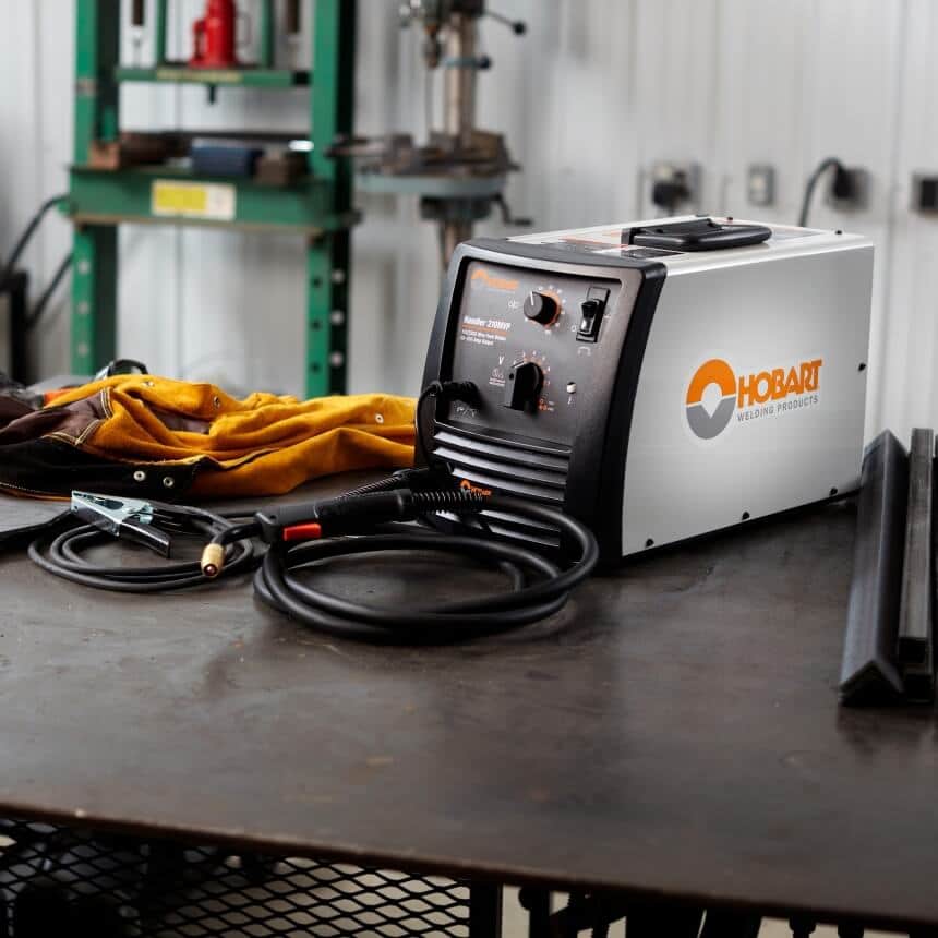
As well they can help you prepare to use any kind of machine. The Forney Easy Weld 100 ST Stick Machine is a good example of a user-friendly machine that can provide an impressive output with weld symbols to follow.
Welding and brazing symbols (as well as terms and other specifics) come in two main standardized forms. The first is the International Organization for Standardization standard (ISO 2553), and the second are the standards from the American Welding Society (ANSI/AWS A2.4-98).
ISO weld symbols and AWS symbols, as well as the terms used, are different in some cases.
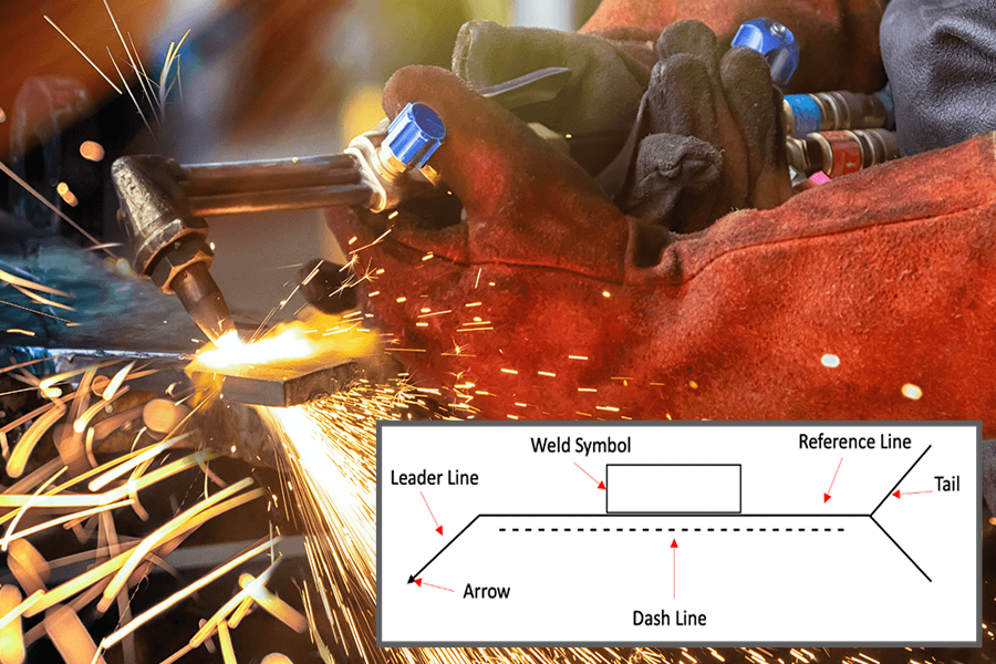
There are a few different parts that are common to welding symbols, and it’s important to know what each of them does.
If you’re interested in serious welding, please check out our takes on the best multi-process welder and the best MIG welder under $500.
Below is a breakdown of weld symbols explained.
This is the horizontal “baseline” of every welding symbol. It is drawn near the weld joint, and other information and symbols are all drawn around or on the reference line.
The arrow connects the reference line as the joint of the weld and goes at either end of the reference line. It can point in any direction, and there can be more than one arrow on a drawing.
On every weld symbol, there is the arrow side (where the arrow points) and the other side of the reference line. This is important when placing the other aspects around the weld joint. In ISO standards, the arrow side information goes above the reference line, while om AWA it goes below the reference line.
More than one arrow can be used on a welding symbol to save space but only when all joints they point to are meant to be welded exactly. When an arrow changes direction or geometry, it means a joint has come to an end.
The tail sits at the end of the reference line on the opposite end of the arrow and is shown by a greater than (>) or less than (<) symbol. This is where information that is required but does not have another specific place is put, either to the left or the right depending on the information. An example of tail-appropriate information is a reference to the welding procedure specification which is being used. This can include, in some cases, all the details for a specific joint. In these cases, a symbol with just an arrow, reference line, tail, and WPS info can be enough to complete a welding job perfectly!
There are several letters that can be used to describe the processes used in the weld, and the AWA standard has two specific lists (one which groups process by type and one alphabetical).
The welding process to be used is often specified by entering process designation letters in the tail of the welding symbol. The American standard includes two lists of processes and their corresponding designation letters. Table 1 groups similar processes, such as arc welding, brazing, resistance welding, and thermal cutting, while Table 2 arranges the processes alphabetically.
There are eight total elements possible in a welding symbol, with only the three mentioned above as mandatory for every complete weld symbol. The eight elements are:
Any combination of the above, so long as the first three are included, is possible.
Letters are used to symbolize various parts of the weld, and their use can vary depending on the type of weld.
The most commonly used symbols are T (tail), S (size, strength, or depth), E (effective throat size), R (root opening), A (angle), F (method of contour), — (place of contour), L (length), P (spacing), and N (number of welds)
Familiarizing yourself with the basics of weld symbolism is the best way to quickly get used to the different methods that might be used in your projects. Even if you’re working with a personal tool like the LOTOS MIG175 on a personal job, it’s still a good idea to use weld symbols.
Some of the most common welding joints and their symbols are described below. You can find images of common groove weld symbols, bevel weld symbols, and more here (ISO) and here (AWS).
These welds are used for edge-to-edge joints, T joints, and corner joints, as well as sometimes to join a flat piece to a curved piece. The different symbols mostly indicate which parts are to be joined together and how their edges should be prepared. The metal goes into the groove, penetrates, and fuses with the base metal, and this is how the joint is created.
Different types of groove weld include:
Square Groove Welds
Tight fits or slightly separated edges. It’s indicated by two parallel vertical lines, and the amount of separation is indicated on the symbol, if there’s any separation at all.
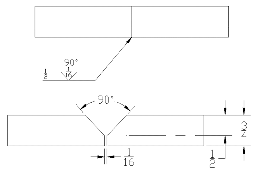
V Groove Welds
These are single or double-beveled edges that create the groove. Any separation at the root and the angle of the V are shown on the symbol. When the depth of the V isn’t the total thickness, it goes to the left of the symbol. If the penetration depth is higher than the groove depth, then the effective throat is given in brackets next to the V depth.
These are when one edge is beveled, and the other is square. The symbol always has a perpendicular line on the left-hand side. There’s an arrow in the symbol to show which piece is to be beveled, and there’s a break in the arrow line for emphasis unless it doesn’t matter which piece has its edge treated. The angle, depth, effective throat, and root separation are marked in the same way as in the V groove weld symbol.
Both edges, in this case, are treated to be concave. The edge treatment’s depth, the throat, and the separation of the roots are marked in the same way as the V groove symbol.
In this case, one age is treated to be concave, and the other remains square. The J groove associates with the U groove in the same way the bevel groove associates with the V groove. The perpendicular line is always on the left-hand side, and the arrow with its (usual) break shows the part that gets the treatment. The depth, effective throat, and separation are marked in the same way as the V groove.
The edge of one of the pieces is given a concave treatment, and the other is left square. It is to the U-groove weld what the bevel groove weld is to the V-groove weld. As with the bevel, the perpendicular line is always drawn on the left side, and the arrow (with a break, if necessary) points to the piece that receives the edge treatment. The methods discussed in the V-groove section describe the depth of edge treatment, effective throat, and separation at the root.
These join two parts that are round or curved. The intended depth of the weld is shown on the left, and the weld depth formed by the two surfaces follows in brackets.
This kind of weld joins curved pieces to flat pieces. The depths are shown in the same manner as the flare V groove. The perpendicular line is always shown on the left-hand side of the drawing.
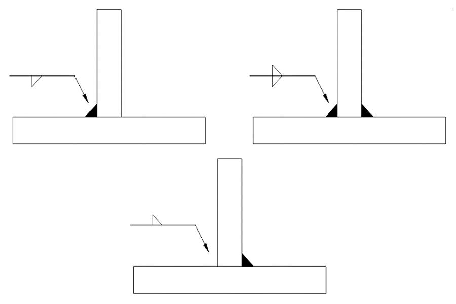
Lap joints, T joints, and corner joints can be made by the extremely common fillet weld. It is a triangular weld and probably the most common weld you’ll find, though it isn’t always right-angled or isosceles in the end. The metal goes in a corner formed by the two pieces and fuses to make a joint after penetrating the base metal.
Regardless of the orientation of the weld, the perpendicular part of the triangle is always on the left-hand side of the symbol. On the left, the leg size is written. When the leg sizes are equal, only one number is there. Less commonly, there are unequal legs, and both dimension numbers are written. It’s also indicated on the drawing which line is which.
The weld’s length goes on the right-hand side of the symbol. When there is no length, the weld goes between dimension lines or points with abrupt changes.
In intermittent welds, each length number is separated by a dash on the right of the fillet weld symbol. The spacing is the end-to-end distance rather than just the clear space.
Plug welds and slot welds are both very similar. In fact, the only major difference is that slot welds use elongated holes and plug wells use round holes. In both cases, two overlapping pieces are joined where one of the pieces has holes in it. The weld metal goes through the holes before penetrating and fusing with the base metal and forming the joint.
The symbols for these welds are also a little different. For plug welds, the diameter of each plug, as well as the spacing (or pitch) between the plugs, are given to the left and right of the symbol, respectively.
For slot welds, you’ll find the width of each slot to the left of the symbol and the pitch and length, separated by a dash, on the right.
In both, the number of slots or plugs is either above or below the symbol in brackets.
Using the arrow side and another side, you can quickly see which piece has the holes. In cases where the hole isn’t supposed to be totally filled with the welding metal, the depth that does need to be filled will also be written with the symbol.
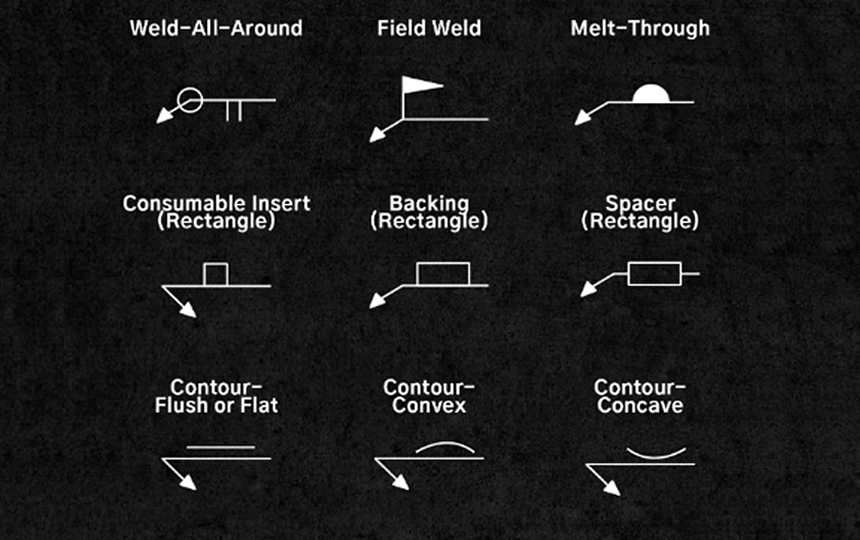
Some symbols are used alongside major symbols in order to supplement or elaborate upon the detail needed in a particular weld. Two common ones used with groove wells are the melt-through and the backing bar symbols, both of which indicate that full penetration must be made with a single-sided groove weld.
Melt-throughs require root reinforcement using more welded metal on the joint’s back side, and this reinforcement’s height is usually shown on the left of the melt-through symbol. You will find the melt-through symbol across the reference line from where the basic symbol lies.
In the case of a backing bar, that symbol will instead be across the reference line from the weld symbol, and there will be a letter inside the backing bar symbol. If the bar is only to stay temporarily and to be removed after the weld is done, then there will be an R within the symbol. Permanent backing will be marked with an M.
Some other kinds of supplementary symbols include:
Certain specific welding processes are indicated by letter combinations. A sample of these designations covering a few different types of welding processes are indicated in the table below.
| Torch brazing | TB | Flow welding | FLOW | Submerged arc welding | SAW | Shielded carbon arc welding | SCAW |
| Twin carbon arc brazing | TCAB | Flash welding | FW | Gas tungsten arc welding | GTAW | Flux cored arc welding | FCAW |
| Furnace brazing | FB | Upset welding | UW | Gas metal arc welding | GMAW | Non-pressure thermit welding | NTW |
| Induction brazing | IB | Percussion welding | PEW | Atomic hydrogen welding | AHW | Pressure thermit welding | PTW |
| Resistance brazing | RB | Induction welding | IW | Shielded metal arc welding | SMAW | Pressure gas welding | PGW |
| Dip brazing | DB | Bare metal arc welding | BMAW | Twin carbon arc welding | TCAQ | Oxyhydrogen welding | OHW |
| Block brazing | BB | Stud welding | SW | Carbon arc welding | CAW | Oxyacetylene welding | OAW |
| Flow brazing | FLB | Gas shielded stud welding | GSSW | Gas carbon arc welding | GCAW | Air-acetylene welding | AAW |
There are many more for every process you can imagine. With some exceptions, as you can see, these designations are fairly self-explanatory to those who are familiar with the standardized terms used in welding and construction.
Cutting processes can also be denoted with letters. A sample of these can be found below:
| Arc cutting | AC | Oxygen cutting | OC | Automatic cutting | AU |
| Air carbon arc cutting | AAC | Chemical flux cutting | FOC | Machine cutting | ME |
| Carbon arc cutting | CAC | Metal powder cutting | POC | Manual cutting | MA |
| Metal arc cutting | MAC | Arc oxygen cutting | AOC | Semi-automatic cutting | SA |
Certain symbols are listed on the welding symbol to indicate that a particular finish is required for the job in question. These are mostly, though not exclusively, used in fillet wells. The most common finish symbols are:
These are usually followed by a number to indicate the required degree of finish for each method.
Brazing symbols are very close to welding symbols both in function and form. Brazing symbols also use the arrow – reference line – tail configuration in the same way that welding symbols do, though some of the actual symbols used are different. Root openings and gaps are much more emphasized in brazing symbols than they are in symbols that focus on fusion welding.
As of now, brazing usually relies more on detailed drawings than on symbols, but the use of brazing symbols is increasing.
Non-destructive examination symbols or NDE (also called non-destructive testing or NDT) are an important part of construction and ensuring that materials, structures, systems, and so on are all up to code. NDE symbols have the exact same arrow, reference line, and tail as a weld symbol, and each part functions in the same way. Examination methods are each assigned a letter, and these letters are placed around the reference line, paying close attention to the arrow side, the other side, and both sides of the part.
They can also be used to show how examination types will be combined using additional letters and signs to join or separate these letters. There are also specific symbols for “field examination” and “examine all around”, just like the supplemental symbols for welding.
Obviously, we’ve only brushed the surface of what weld symbols offer, but even with this introductory crash course, you are well on your way to using them efficiently and well during each job! The most important part is knowing the key basic weld symbols, how each should be used, and how these symbols can be combined to make a foolproof blueprint for your project.
In a way, each weld symbol is like a letter, and the ISO and AWA standards are like a written shorthand language. Knowing proper welding terms is knowing how to speak that language while using the right weld symbols is how you write it down and communicate with others. So practice, practice, and practice some more – and soon, you’ll be doodling these symbols without a second thought!